4-20ma loop powered wiring diagram 4 20ma loop powered wiring diagram 4 20ma wiring diagram
How to do the 4-20mA Wiring? | Instrumentation and Control Engineering
Fundamentals, system design, and setup for the 4 to 20 ma current loop
Current loop connection
Wire 20ma transmitter sensor transmitters voltage background instrumentCircuit diagram power loop test loop How to do the 4-20ma wiring?20ma sensor loop current ma 20 signal power receiver system wire circuit setup supply isolated ni io connected fundamentals share.
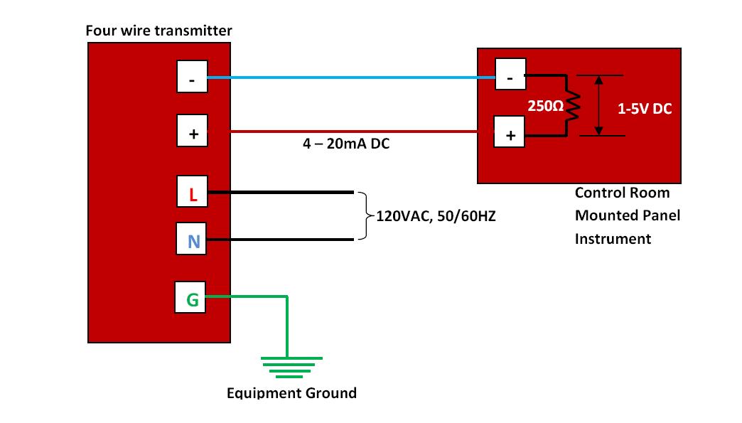
2-wire 4-20 ma sensor transmitters: background and compliance voltage20ma wiring transmitter wire control instrumentation wires 4-20ma analog signal loop with power supplyLoop wiring diagram wire current connection 20ma ma 20 divize sensor converter voltage signal tide arduino examples power tester supply.
![4 20ma Loop Powered Wiring Diagram](https://i2.wp.com/www.electroschematics.com/wp-content/uploads/2014/04/MAXREFDES15.png?w=1139)
4 20 ma circuit diagram
Connecting 4-20 ma outputs : rheonics supportImpedance ohms 4 20ma loop powered wiring diagramCurrent loop circuit diagram.
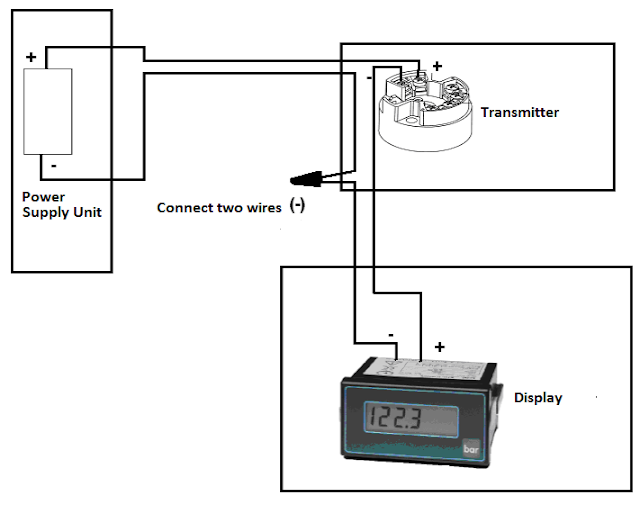
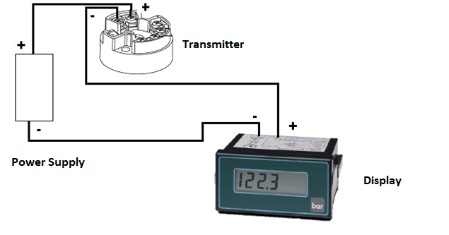
Loop powered 4-20ma wiring4-20ma loop powered wiring diagram 4 20ma loop powered wiring diagramBasics of the 4.
![4-20ma Loop Powered Wiring Diagram](https://2.bp.blogspot.com/-HgrIw6YKLnE/TWf9qzaQX4I/AAAAAAAAAHM/YA2dTsiuek0/s1600/Four+wire+transmitter.jpg)
4 20ma wiring diagram
4-20ma loop powered wiring diagram[diagram] easy wire loop diagrams 4-20ma loop powered wiring diagram.
.
![4 20ma loop powered wiring diagram](https://i2.wp.com/airconditioningmanuals.tpub.com/TM-5-4120-364-13/TM-5-4120-364-130026im.jpg)
![4 20ma Wiring Diagram](https://4.bp.blogspot.com/-s3Y8jYpxtBU/W-IbWIBRFyI/AAAAAAAAAjc/oFTLVVQyBKgevAkcgINSG8zXtTxVILLSACLcBGAs/w1200-h630-p-k-no-nu/How%2Bto%2BWire-4-20%2BmA%2BLoop.png)
![4-20ma Loop Powered Wiring Diagram](https://i.pinimg.com/originals/8c/59/28/8c59287df12ef6ec830a9150a9de4e49.png)
![4-20mA analog signal loop with power supply - Ewon Flexy - hms.how](https://i2.wp.com/forum.hms-networks.com/uploads/default/original/3X/c/b/cb33f35d02c80cd63f7877c8dba3ede97be14c3c.png)
![[DIAGRAM] Easy Wire Loop Diagrams - MYDIAGRAM.ONLINE](https://i2.wp.com/instrumentationtools.com/wp-content/uploads/2018/03/Two-wire-loop-powered-transmitters.png)
![4 20ma Wiring Diagram](https://1.bp.blogspot.com/-x8K6Bfegpg8/W-IbtPTPQGI/AAAAAAAAAjo/QlGVwL9z0DEs2KU0l3CGSK4n_uDTEdOywCLcBGAs/s640/How%2Bto%2Bwire%2B4-20%2BmA%2BLoop%2B01.png)
![Basics of The 4 - 20mA Current Loop ~ Learning Instrumentation And](https://4.bp.blogspot.com/-TJKTjBZqxWw/T2zOzVw-XyI/AAAAAAAAAR0/oFh9Mu9tRTY/s1600/4+-+20mA+Current+Loop+Circuit.jpg)
![Circuit Diagram Power Loop Test Loop](https://i2.wp.com/www.instrumentationblog.com/wp-content/uploads/2020/10/4-20-mA-Current-Loop-with-Fuse.jpg?w=1034&ssl=1)
![2-Wire 4-20 mA Sensor Transmitters: Background and Compliance Voltage](https://i2.wp.com/e2e.ti.com/resized-image/__size/1230x0/__key/communityserver-blogs-components-weblogfiles/00-00-00-09-30/5633.Figure1.jpg)
![How to do the 4-20mA Wiring? | Instrumentation and Control Engineering](https://i2.wp.com/cdn.automationforum.co/uploads/2021/11/image-63.png)